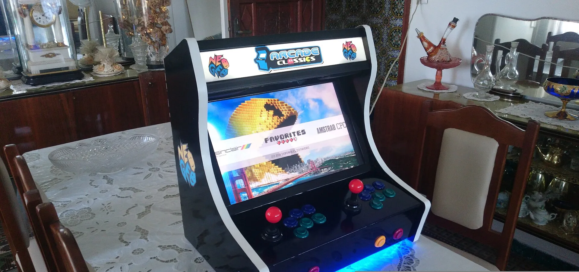
Build a Bartop Arcade Cabinet with a Raspberry Pi
A weekend build: a two-player bartop arcade machine with real joysticks and buttons, a spare monitor and a Raspberry Pi running Batocera. Parts list, kit vs scratch-built, wiring the controls and setting it up.
What You’re Building
A bartop is a compact arcade cabinet that sits on a table or counter: a screen in a wooden case, with a control panel of joysticks and buttons in front. Inside, a Raspberry Pi runs Batocera, which boots straight into a menu of arcade and console games. It’s the most satisfying retro project there is: you end up with a real piece of furniture that people walk up to and play.
About games: use arcade and console games you own, or the large world of free homebrew games; Batocera includes some free ones. Arcade ROM sites mostly distribute copyrighted games without permission.
Kit or Scratch-Built?
- A flat-pack kit (pre-cut MDF panels, often with the control-panel holes drilled, and sometimes with art and controls included) is the easiest route. Check which monitor size it’s designed for before buying.
- Scratch-built from free bartop plans means cutting MDF yourself with a jigsaw or circular saw. It’s cheaper and fully customizable, but plan on an extra weekend.
Either way, choose the monitor first: everything is sized around it.
Parts List
- Raspberry Pi 5 (or Pi 4) with cooling, the official power supply and a 64GB+ microSD card
- A monitor, typically 17–19 inches. Old 4:3 monitors suit classic arcade games, whose screens were nearly square; a 16:9 monitor works with black bars at the sides. It needs HDMI (or DVI with an adapter).
- Controls for two players: two 8-way joysticks and 12–16 arcade buttons (6 per player plus Start, Coin/Select and an exit button). “Sanwa-style” or similar 30mm buttons are the common size.
- Two USB encoders (often sold as “zero delay” encoder kits with joysticks and buttons): small boards that turn joystick and buttons into a USB controller, with the wiring included
- Speakers: a small USB-powered or amplified speaker pair, plus a USB audio adapter on the Pi 5 (which has no headphone jack), or use the monitor’s speakers via HDMI
- A power strip mounted inside, with one switch for everything
- Wood glue, screws, a drill with a 28mm spade or Forstner bit for the buttons, and optional T-molding for the edges and vinyl art for the sides
Step 1: Build the Cabinet
Assemble the sides, base, back, top and monitor shelf following your kit’s instructions or plans. Two tips:
- Make the back panel removable (screws, not glue), so you can reach the Pi and wiring later.
- Leave airflow: drill a few vent holes near the top of the back panel. The Pi and monitor both make heat.
Step 2: Lay Out and Drill the Control Panel
Print a template of a standard button layout at full size, tape it to the control panel, and drill.
- Joysticks on the left, buttons in two curved rows of three to the right for each player: a common “fighting game” layout.
- Start and Coin buttons above or between the players, and an extra button at the edge as a hotkey/exit button.
- Drill a test hole in scrap wood first; button holes are usually 28mm for 30mm buttons.
Mount the joysticks underneath the panel (most attach with four screws), clip the buttons in from the top, and fit the control panel to the cabinet with hinges or screws so you can open it.
Step 3: Wire the Controls
Each USB encoder handles one player:
- Connect each joystick’s cable to the encoder’s joystick port.
- Connect each button to an encoder input with the supplied wires. The plug-in “zero delay” kits need no soldering.
- Plug both encoders into the Pi’s USB ports.
Write down which button goes to which encoder input; it makes mapping easier.
Step 4: Fit the Monitor, Pi and Speakers
- Mount the monitor behind the bezel opening, on the monitor shelf or brackets.
- Fix the Pi to the inside of the cabinet with its case or standoffs, where its cooler gets air.
- Connect HDMI, the speakers and the encoders, and plug everything (monitor, Pi, speakers) into the internal power strip. Run the strip’s switch, or a panel-mount switch, to the back so one switch turns the whole machine on.
Electrical safety: keep mains wiring to standard plugs and a power strip, which is the reason to use one. Don’t splice mains cables unless you’re qualified.
Step 5: Set Up Batocera
Flash Batocera and add games as in our Batocera tutorial. Then map the controls:
- When Batocera starts, it detects the encoders as two controllers. Go to the main menu → Controller & Bluetooth Settings → Controller Mapping, and map player 1’s joystick and buttons as prompted. Repeat for player 2.
- Choose which button is the hotkey, such as the extra exit button: hotkey + Start quits a game, which is how players get back to the menu without a keyboard.
- In the controller settings, check player 1 and player 2 are assigned to the right encoders.
Step 6: Finishing Touches
- Art: printed vinyl side art, a backlit marquee at the top, and T-molding around the edges make it look like the real thing.
- Screen settings: in Batocera’s game settings, keep arcade games in their original shape rather than stretching them to a wide screen.
- Sound: set the volume once in Batocera and use the speakers’ knob day to day.
- Attract mode: Batocera can show a screensaver that plays game demos while nobody’s playing, which is great for drawing people in.
Troubleshooting
A joystick moves the wrong way: many joysticks can be rotated, or remapped in Batocera’s controller mapping. Check the wiring direction matches the encoder’s labeling.
Players are swapped: reassign player 1 and 2 in Batocera’s controller settings, or swap the encoders’ USB ports.
No sound: on a Pi 5, select the USB audio adapter (or HDMI) in Batocera’s sound settings; the Pi 5 has no headphone jack.
The Pi overheats in a closed cabinet: add vent holes or a small USB fan, and make sure the Pi’s own cooler has space around it.